




30°, 45° or 60°? What Bed Angle Really Changes on a Slant Bed CNC Lathe
Slant Bed CNC Lathe · Angle Selection Guide
Two builders can quote the same eight-inch chuck, the same control package and the same twelve-station turret, then deliver machines that behave nothing alike once the first interrupted cut starts. On a slant bed CNC lathe, the angle of the bed is one of the reasons. It sets the direction in which cutting force reaches the guideway, the speed at which hot chips leave the work zone, how much of the saddle’s own weight the feed drive has to hold, and how far an operator reaches to change an insert. This guide compares 30°, 45° and 60° machines on those four points, then shows how to match an angle to a part family instead of to a catalogue page.
Key Takeaways
A slant bed CNC lathe turns cutting force toward the casting: the steeper the bed, the larger the share of radial force that presses into the guideway instead of sliding along it.
30° beds keep the gravity load on the feed drive low and leave the most room in front of the spindle, which suits small, high-speed parts and machines that still need hand access.
45° is the angle most builders settle on because it splits vertical and radial force evenly without pushing chip clearance, machine height or footprint to an extreme.
60° beds clear chips and coolant fastest and bring the tool point closest to the operator on large work, but roughly 87% of the saddle’s weight then pulls along the incline.
The angle alone does not decide rigidity. Casting construction, guideway type, ball screw preload and thermal behaviour usually move the result more than the 15° between one bed and the next.
What the Bed Angle Changes on a Slant Bed CNC Lathe
On a flat bed machine the guideway is horizontal and the saddle sits on top of it. The radial cutting force — the component that pushes the tool away from the workpiece — runs parallel to that guideway, so the saddle is pushed sideways along the bed rather than pressed into it. A slant bed rotates the whole arrangement. The guideway is inclined, the saddle rides on the upper face, and part of the radial force now acts straight down into the casting. That single geometric change is the reason the two machine types behave differently, and it is worth seeing why before comparing angles.
The wider slant bed vs flat bed lathe comparison is covered in this look at slant bed and flat bed lathe layouts, which sets out the structural and cost differences in more detail.
The cutting force, split in two directions
Every turning operation produces two force components at the tool tip: a vertical component that pushes down, and a radial component that pushes the tool away from the work. On an inclined guideway, the share of the vertical component acting perpendicular to the bed is the cosine of the bed angle, and the share of the radial component acting perpendicular is the sine. At 30° those shares are 87% and 50%. At 45° they are both 71%. At 60° they are 50% and 87%.
The same trigonometry fixes the cost as well, because it also decides how much of the saddle’s weight pulls down the slope: none on a flat bed, 50% at 30°, 71% at 45° and 87% at 60°. A steep bed buys stiffness against lateral force and pays for it with a constant load on the ballscrew, the thrust bearing and the servo brake.
Table 1. How the bed angle redistributes load (percentages are exact trigonometric shares of each component)
| Bed angle | Vertical force into the bed | Radial force into the bed | Weight pulling along the bed | Chip clearance |
|---|---|---|---|---|
| Flat bed (0°) | All of it | None | None | Chips rest on the ways |
| 30° | 87% | 50% | 50% | Fair; some chips reach the lower cover |
| 45° | 71% | 71% | 71% | Good for most materials |
| 60° | 50% | 87% | 87% | Chips fall clear without help |
Chip evacuation and coolant drainage
Chips leave the cutting zone hot and they leave it fast. On a horizontal bed they land on the surface the saddle has to travel over, and the wipers drag them back under the guideway on the return stroke. On an inclined bed gravity takes them to the chip conveyor instead. The steeper the incline, the shorter the path and the less contact with the machine structure. At 30° a share of the chips still settles on the lower way cover, and stringy swarf from gummy aluminium can bridge across the opening. At 45° and above, most of the chip load clears without assistance.
Coolant follows the same route. A sloped bed drains back to the tank instead of pooling around the saddle, which keeps fluid from sitting against seals and from carrying fines back into the ways.
Footprint, height and operator reach
Tilting the bed also changes the machine envelope. A 30° bed is lower and deeper: the workpiece centreline sits closer to the floor, the bed spreads out behind it, and the operator reaches over a wider horizontal gap to change jaws. A 60° bed is taller and narrower, with the spindle face presented almost vertically, so the operator works in front of the chuck rather than above it. In a shop with a low crane rail or a tight ceiling, that difference can decide which machine fits at all.
30° Slant Bed CNC Lathe: Gentlest Incline, Widest Working Room
A 30° slant bed CNC lathe keeps the guideway closer to horizontal than either alternative. Of the vertical cutting force, 87% still presses into the bed, so the machine is not short of support under a normal turning pass. The radial component contributes only 50% of its magnitude as normal load, and the rest acts along the guideway. The saddle is therefore easier to push sideways — which is exactly what an interrupted cut or a deep radial engagement tries to do.
Where a 30° bed earns its place
Small precision parts run at high spindle speed and light depth of cut, where force is modest and the priorities are reach, thermal stability and fast setup.
Gang-tool layouts put the tool plate close to the spindle; a shallow incline keeps that plate accessible and shortens the tool change path.
Machines that still need hand access for deburring, gauging or a second operation benefit from the lower, more open front.
Low buildings and low crane rails: a 30° machine is shorter than a 60° machine of the same swing.
Where it runs out of room
Heavy interrupted cutting on hard material is the weak case. The radial force has a large component along the guideway, so the saddle is loaded in the direction it is designed to slide. Box guideways and a heavier saddle recover part of that loss, and builders who fit them often do so precisely because the bed angle is shallow. Long, stringy chips are the second weak case: they can still catch on the lower way cover and need a conveyor with enough pull to clear them. Large swing work is the third — at 30° the bed spreads outward rather than upward, so floor area grows faster than height.
45° Slant Bed CNC Lathe: Why Most Builders Settle Here
At 45° the two components arrive in equal measure: 71% of the vertical force and 71% of the radial force act perpendicular to the guideway. Neither direction is favoured, so the angle behaves predictably across steel, stainless and cast iron at moderate depth of cut. It is also the angle around which the widest range of turrets, tailstocks, Y axes and sub-spindles has been engineered, because it is the volume platform that component suppliers build for.
The balance point in practice
A 45 degree slant bed CNC lathe clears chips reliably for most materials without the height penalty of a steeper bed. The chip path is short enough that gravity does most of the work, and the lower way cover sits far enough back that wiper damage from hot chips is uncommon. Coolant drains cleanly. The operator faces the spindle at a comfortable angle, and the machine still fits under a standard workshop crane.
What 45° does not solve
It does not turn a light machine into a heavy one. Roughing a 300 mm forged flange still depends on casting mass, guideway section and spindle torque, not on fifteen degrees of bed angle. It does not fix chip bridging in gummy aluminium, where stringy swarf can pack against any incline. And it does nothing for a long, slender shaft, where a tailstock, a steady rest and tool geometry decide the result long before the bed angle does.
60° Slant Bed CNC Lathe: Steep Enough for Hard, Hot and Complex Work
A 60° bed inverts the 30° balance. Half of the vertical force now presses into the bed and 87% of the radial force does, so lateral deflection under a heavy or interrupted cut meets a much stiffer reaction. The chip path is the shortest of the three, and on a large machine the tool point is presented near the operator’s chest height instead of knee height.
What the extra 15 degrees buys
Lateral stiffness: 87% of the radial force goes into the casting, which matters on hard turning and on cast or forged surfaces that interrupt the cut.
Chip and coolant clearance: swarf leaves the work zone almost vertically, so less heat is held near the saddle and less coolant reaches the ways.
Access on large work: with a 400 mm or larger swing, a steep bed brings the turret and the chuck face toward the operator instead of leaving them below eye level.
Separation on multi-turret machines: twin-spindle and twin-turret layouts use the steep bed to keep the two working zones apart, so chips from the first operation do not reach the second.
What it costs
The gravity load is the price. At 60° about 87% of the saddle’s weight pulls along the incline, so the Z-axis ballscrew, thrust bearing and servo brake carry a permanent load and the drive has to be sized for it. A machine with an undersized drive will drift when the servo releases, wear the ballscrew faster and run hotter at the thrust bearing. The envelope is the second cost: a 60° machine is taller, and the chip conveyor and coolant tank often sit further out from the base. The third is choice — fewer standard configurations exist at 60°, so more of the machine is engineered to order.
30° vs 45° vs 60°: Side by Side
The table below puts the three angles on one scale. The force shares are trigonometric rather than measured: they follow directly from resolving the cutting force against the guideway. The remaining rows describe how each angle is used in practice.
Table 2. What each bed angle changes across the machine
| What it decides | 30° | 45° | 60° |
|---|---|---|---|
| Radial force reaching the casting | 50% | 71% | 87% |
| Continuous load on the Z-axis drive | Low | Moderate | High |
| Chip clearance without assistance | Fair | Good | Fastest |
| Machine height for a given swing | Lowest | Medium | Highest |
| Access to the tool point on large work | Reach over the bed | Angled front | Nearly vertical |
| Range of standard configurations | Moderate | Widest | Narrowest |
| Part family that fits it | Small precision work at high spindle speed | General turning, shafts, valve bodies | Heavy or interrupted cuts, twin-spindle work |
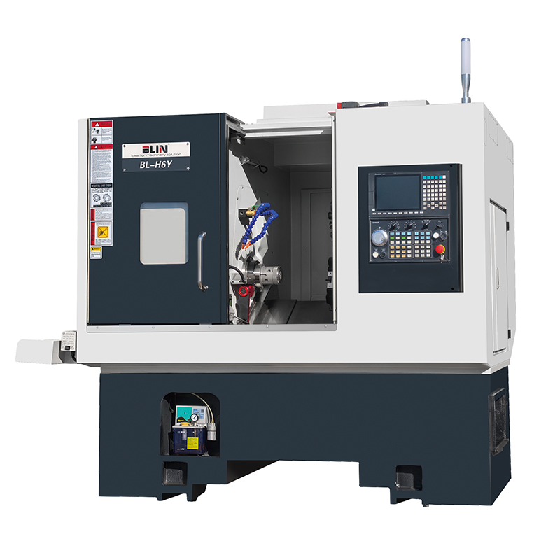
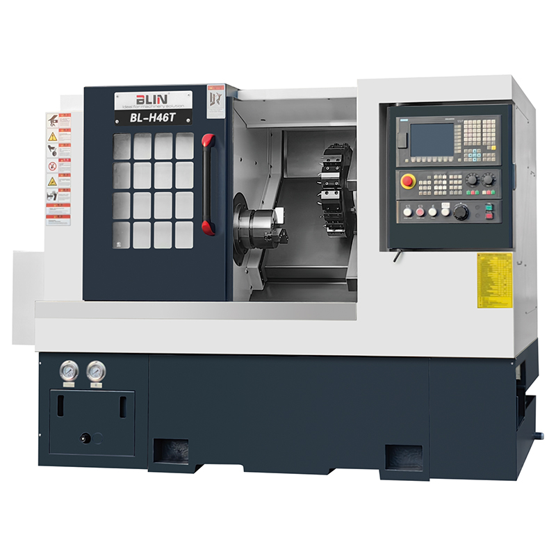
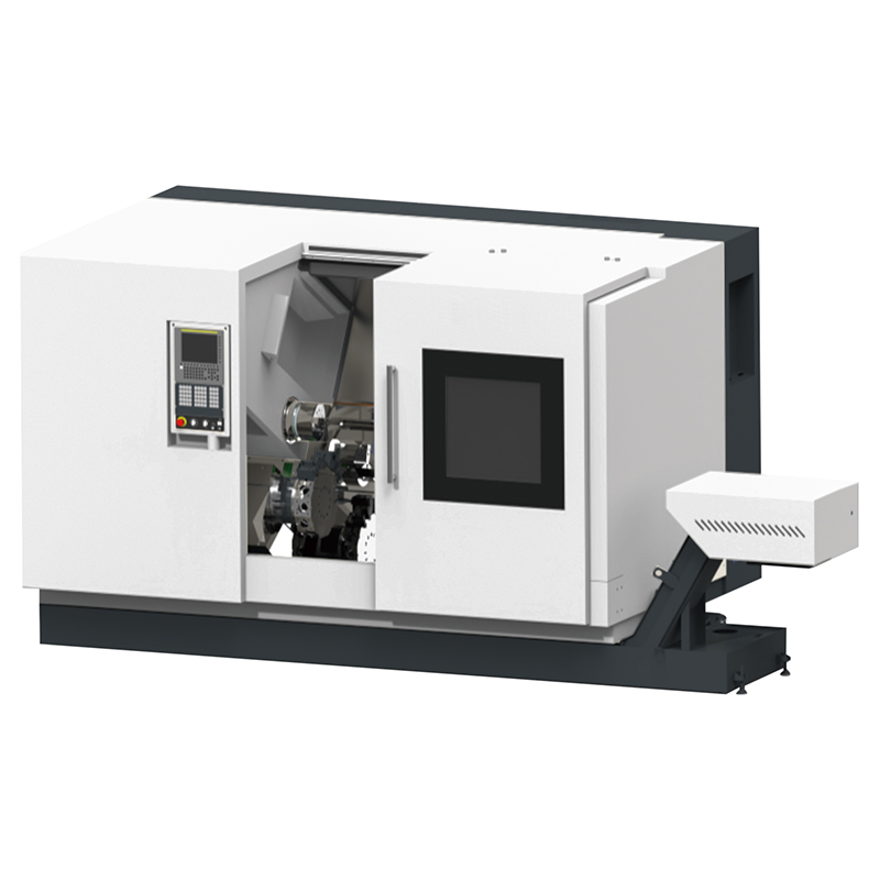
All three angles are in production at BLIN, and the three machines below show what each one looks like when it is built around a specific job rather than a catalogue tier.
Matching the Angle to the Part, Not to the Brochure
Most buying mistakes come from fixing the angle before fixing the part family. A shop that runs 20 mm connectors and a shop that runs 400 mm valve bodies need different machines even when their chuck sizes overlap, and the reason is the load path rather than the price. Working in that order — part first, then load, then angle — is the practical answer to how to choose a slant bed CNC lathe without overpaying for capacity the work will never use.
Small parts at high spindle speed
Below roughly 60 mm diameter, cutting force is small and cycle time is dominated by tool change and spindle acceleration. A 30° or 45° machine with gang tooling or a fast turret usually wins, because the bed angle is not the limiting factor and the open front shortens every setup.
Long shafts and heavy, interrupted cuts
Above roughly 200 mm diameter, or wherever the tool enters a cast or forged surface, lateral force dominates. A 45° machine with box guideways is the common answer. A 60° bed, or a heavy-duty 45° platform with a wide box way, is the answer when the cut is genuinely interrupted and the material is hard. What separates the two is mass and guideway section, not the number on the drawing.
Turn-mill work with a Y axis
When a part needs milling, drilling and tapping in one clamping, the bed angle has to leave room for a powered turret and its Y-axis travel. A 45° bed is the usual base for that layout. At 60° the turret sits closer to the spindle centreline, which shortens Y travel and complicates tool clearance on large diameters.
Table 3. Angles worth shortlisting by part family
| Part family | Typical size | Dominant load | Angle to shortlist |
|---|---|---|---|
| Connectors, pins, sensor bodies | Ø5–30 mm | Low; cycle time dominates | 30° with gang tooling |
| Valve cores, drive shafts | Ø20–80 mm, up to 600 mm long | Moderate radial, some interruption | 45° |
| Automotive shafts and hubs | Ø60–200 mm | Radial plus axial thrust | 45° with tailstock |
| Valve bodies, pump housings, flanges | Ø150–400 mm | Heavy and interrupted | 45° box way or 60° |
| Large casings, mining and oil field parts | Ø400 mm and above | Heavy, continuous or interrupted | 60°, or a heavy-duty 45° platform |
Not sure which angle your part family needs?
Send the drawing, the material and the batch size. A turning specialist will tell you which bed angle and way form the job actually calls for, and which of the two costs less over the life of the machine.
Get a QuoteBeyond the Angle: What Else Decides Rigidity
Two machines can share a 45° bed and still differ by a factor in stiffness. The angle sets the direction of the load path; the structure decides how much load that path can carry.
The bed casting and how it is damped
A mono-block casting that combines bed and base into one piece removes a bolted joint from the load path, and bolted joints are the softest element in any machine structure. Rib layout, wall thickness and the grade of cast iron set how far the bed deflects and how quickly it stops ringing. HT300-class iron, stress-relieved by aging and checked by finite element analysis before the pattern is cut, is the usual specification at this level. Published work shows why the detail matters: a finite element study of a large CNC lathe bed reported a maximum deformation of 0.1455 mm and a first natural frequency of 271.63 Hz — figures a builder has to design against rather than discover on the shop floor.
Guideway type: roller linear or box
Roller linear guideways run with low friction, hold preload well and suit high-speed axes. Box guideways, hand-scraped and flood-lubricated, add damping that no linear rail matches, which is why they survive interrupted cuts and hard material. The choice is not a quality ranking; it is a match between the axis duty and the way form. Machines built for heavy turning, such as the BL-S300 heavy-duty slant bed CNC lathe series, usually offer both and let the buyer choose.
Thermal behaviour
Heat moves the tool relative to the work, and on a slant bed the geometry decides how that movement shows up in the diameter. Research on a high-precision slant bed lathe separated the contributions of spindle, turret and bed to the measured thermal drift and found that the tilt angle changes how each error projects into the X direction — which is why a thermal model built for one bed angle does not transfer unchanged to another. See this study of spindle thermal error on a slant bed lathe for the method.
Three measures carry most of the benefit in practice: pre-tensioned ballscrews with double nuts, a spindle with controlled preload, and compensation tables built from a warm-up test. None of them depend on the bed angle, and all of them matter more than a 15° difference.
Ball screw, thrust bearing and servo sizing
On a steep bed the drive fights gravity all day. A Z-axis sized for acceleration alone will hold position but run hot; one sized for the continuous gravity component as well will hold position and last. Ask for the continuous thrust rating against the saddle mass, not just the rapid traverse speed.

How to Verify a Slant Bed CNC Lathe Before You Sign
A bed angle is a line on a drawing. A machine is a set of measurements. The gap between the two is where most acceptance disputes begin, so it is worth agreeing on the tests before the purchase order rather than after the installation.
Geometric and positioning tests
ISO 13041-1 sets out the geometric tests for numerically controlled turning machines and turning centres with a horizontal workholding spindle, and a supplier should be able to produce a test chart against it. Positioning accuracy is usually reported separately, from a laser interferometer run on each axis. For scale, a recent bed and saddle optimisation study with laser interferometer validation reported 3.0 μm on X and 3.3 μm on Z for a horizontal CNC lathe after the structure was stiffened, with measurement uncertainty stated at 0.38 μm and 0.45 μm.
Ask for the uncertainty figure. A number quoted to 0.1 μm without one is a number without a meaning.
The test cut
Cut a part from your own family, not the demonstrator’s. Measure diameter scatter across thirty consecutive parts, roundness on a cylindrical section, and surface finish on both a finishing and a roughing pass. A machine that holds size cold but drifts warm will show up in the scatter long before it shows up in a single inspection report.
Thermal drift
Run a test bar at a representative spindle speed for two hours and measure it at intervals. The shape of the drift curve matters more than the end value: a machine that reaches a plateau in 40 minutes can be compensated, while one that is still climbing after two hours has a cooling or preload problem that no compensation table will hide.
Table 4. Acceptance checks worth writing into the order
| Check | How to test | What good looks like |
|---|---|---|
| Positioning accuracy, X and Z | Laser interferometer, one axis at a time | A stated value with its measurement uncertainty |
| Repeatability | Thirty approaches to the same point | Tight scatter, no trend with time |
| Spindle thermal drift | Test bar cold, then after two hours at working speed | A curve that plateaus rather than keeps climbing |
| Diameter scatter | Thirty consecutive parts from your own family | No drift from the first part to the last |
| Roundness and finish | Roundness tester and surface roughness tester | Inside the tolerance the part actually needs |
| Chip clearance under load | Roughing pass at 70–80% of rated depth | Chips leave without manual clearing |
| Turret indexing | Index through every station, then face a disc | No visible witness mark on the faced surface |
Request a test report before you commit
Geometric charts, laser interferometer results and a test cut on your own part can all be arranged before shipment. Ask for the figures, not the brochure.
Contact UsConclusion
The angle question has a short answer and a long one. The short answer: 30° for small, fast, accessible work; 45° as the default for general turning; 60° when lateral force, chip volume or operator access on large work justifies a heavier drive and a taller machine. The long answer is that the angle only sets the direction of the load path, while the casting, the guideways, the ballscrew and the thermal design decide how much of that load the machine can carry.
A buyer who compares those four things across two candidate machines will usually find that the difference between them is larger than the difference between 30° and 60°. The full buyer guide to choosing a slant bed CNC lathe sets out the rest of the specification checklist, and the slant bed CNC lathe range shows how the two series differ in construction.
Frequently Asked Questions
Is a 45° slant bed CNC lathe always more rigid than a 30° one?
No. The angle changes the direction of the load, not the magnitude the structure can carry. A 30° machine with a heavy mono-block casting and box ways can be stiffer than a light 45° machine. Compare casting mass, way section and ballscrew size before comparing angles.
What does the angle number actually measure?
The inclination of the guideway from horizontal. A flat bed is 0°, and a vertical bed would be 90°. Production machines sit between 30° and 60°, with a few layouts using a shallow 15° bed combined with a slanted Y axis.
Can a 30° slant bed handle heavy cutting?
It handles moderate interrupted cuts when the builder fits box ways and a heavy saddle, but the radial force has a large component along the guideway, so the geometry works against the machine. For continuous heavy roughing, a 45° or 60° bed with a wide box way is the safer starting point.
Why do 60° beds appear on twin-spindle and twin-turret machines?
A steep bed separates the two working zones and sends chips from the first operation straight down and out, so they do not reach the second spindle. It also brings the tool point closer to the operator when the work is large.
Does a slant bed take more floor space than a flat bed lathe?
Usually less for the same swing, because the bed is stacked at an angle instead of spread out behind the spindle. The trade is height: a steep bed makes the machine taller, which matters under a low crane rail.
How can I check the bed angle on a machine I am buying?
Ask for the general arrangement drawing and measure the guideway inclination against the horizontal, not against the machine base. Then confirm the way form and the saddle mass, because those two decide how the angle actually performs in a cut.
Sources
Shi, H., Qu, Q., Mei, X., Tao, T., Wang, H. Robust modeling for thermal error of spindle of slant bed lathe based on error decomposition. Case Studies in Thermal Engineering, Vol. 51 (2023) 103564. doi.org/10.1016/j.csite.2023.103564
Yang, H., Zhao, R., Li, W., Yang, C., Zhen, L. Static and Dynamic Characteristics Modeling for CK61125 CNC Lathe Bed Basing on FEM. Procedia Engineering, Vol. 174 (2017) 489–496. doi.org/10.1016/j.proeng.2017.01.171
Qin, L., Sun, C., Wu, L., Geng, J., Li, L., Shi, B. Static–Dynamic Performance Improvement of LV500 Horizontal CNC Lathe via Bed–Saddle Collaborative Optimization and Laser Interferometer Validation. Machines, Vol. 14, No. 9 (2026) 995. doi.org/10.3390/machines14090995