What Is a CNC Milling Machine? How It Works and How to Choose One
Ask a shop that replaced a manual mill with a CNC milling machine and the answer rarely mentions speed. It mentions repeatability: the same part, cut from the same program late in the evening, matches the one machined at the start of the shift. A CNC milling machine is a cutting machine whose movements are commanded by a computer rather than by the hand of a machinist, and that single substitution changes how a workshop is organized. This guide explains what the machine actually is, what each subsystem contributes, how accuracy should be read, and what a buyer has to settle before a quotation means anything.

Key Takeaways
The machine combines three systems: the cutting machine itself, the motion system that drives it, and the computer control that turns a program into movement. The computer replaces hand positioning, not the physics of cutting.
The vertical machining center is the default configuration for prismatic work; horizontal machines and five-axis gantry or trunnion machines exist for particular envelopes and for parts that must be finished in one setup.
Structure, guidance and thermal behavior decide how a machine feels under load. The resolution of the control matters less than the casting, the guideway and the ball screw it drives.
An accuracy figure means little unless it is stated with a method, a condition and an edition of the test standard used to obtain it.
A CNC milling machine does not remove the need for fixtures, tooling, programming and maintenance. It relocates skill from the hand to the program and the maintenance schedule.
What a CNC Milling Machine Is
A CNC milling machine is a machine tool fitted with a rotating cutter that removes material from a workpiece. The workpiece is held on a table in a vise or a fixture; the cutter is mounted in a spindle that turns at a set speed; and the two are moved relative to one another along three linear axes. X runs left to right, Y runs front to back and Z runs up and down, and a fourth axis of rotation, usually labelled A, B or C, may be added to tilt the table or the spindle head.
What makes the machine a CNC installation rather than a manual mill is not the cutting action but the source of the movement. On a manual mill, an operator swings the table by hand against the cutter. On a CNC milling machine, the operator writes or posts a program, and the controller converts it into coordinated movement of the axes while the operator loads, unloads, changes tools and checks the result.
The difference shows up in three practical ways. Repeatability improves, because the machine returns to the same coordinates instead of to the same feeling. Complexity becomes practical, because a three-dimensional contour that would take hours of manual cranking can be repeated once the program exists. And set-up becomes data: the work offsets, the tool lengths and the tool data live in the control rather than in the memory of the operator.
Compared with a drill press, the added value is not the spindle but the two axes that accompany it. A drill press makes one hole in one position; a milling machine makes any prismatic shape, because the cutter can travel along a path rather than plunge at a point.
The Three Systems Inside Every CNC Milling Machine
The structure. A cast iron base, column, table and spindle head. This skeleton carries cutting force into the floor and defines the machine's envelope and its rigidity.
The motion system. Servo motors, drives, ball screws and guideways. Each axis is a chain from a command to a slide, and every link in that chain contributes to positioning accuracy.
The control and tooling. The controller, the automatic tool changer, coolant delivery, chip removal, guarding and probing. These decide how much of the machine's time is spent cutting rather than waiting.
What the Controller Actually Does
The controller holds the program, usually written in G-code, and reads it line by line. It interpolates the commanded positions into smooth motion for each axis, applies offsets, and sends drive commands to the servo amplifiers. It also manages the tool change sequence, holds the tool data that compensates for different cutter lengths, and can run a probe cycle that finds the workpiece surface and writes the offset automatically.
Machine data is increasingly read directly from the control by monitoring and scheduling software, and the open standard that defines how machine tool data is exchanged between controllers, adapters and monitoring systems is the point of reference for plants that run mixed machine brands under one monitoring system.
What the controller cannot do is compensate for a structure that has moved. A column that has grown thermally by several micrometers, a slide that has lost its preload or a spindle that is running out all produce the same result in the part, whatever the display shows. That is why machine accuracy and control resolution are discussed separately: the first is a property of the machine, the second a property of the electronics.
The Main CNC Milling Machine Configurations
Three arrangements cover most of the machines in service, and they are chosen by envelope, material and part geometry rather than by price alone.
Vertical Machining Centers
In a vertical machining center the spindle sits above the table and the workpiece is presented to it from below. This is the default configuration for plates, housings, brackets and pockets, because loading and unloading happens at the front of the machine where the operator can reach it, and gravity helps the chips fall away from the cutter. The CNC milling machine range published by this manufacturer is organized around vertical centers of different rigidity classes, from box-way heavy cutting machines to precision machines for mold work.
Horizontal Machining Centers
A horizontal machining center points the spindle sideways and rotates the table so that the workpiece presents different faces to a fixed spindle. The advantage is chip evacuation: coolant and air reach the cutter from the side and carry debris away, which is what allows deep cavities to be cut in difficult materials. The trade is a larger footprint and a heavier table drive.
Five-Axis Machines
Adding two rotary axes removes the need to re-clamp a part for a second face. Two families dominate: the trunnion, where the table tilts and rotates with the workpiece, and the gantry or tilting-head arrangement, where the cutter moves around a fixed table. A gantry machine carries the rotating axis over the working area, which suits large workpieces and long travel. Two levels of capability exist: 3 plus 2 machining, where the rotary axes index to a fixed angle and the three linear axes cut, and simultaneous machining, where all five axes move together along one interpolated path. The second removes the stepped finish that appears where a ball cutter meets a curved surface, at the cost of much more demanding programming and collision checking.
The Parts That Decide How a CNC Milling Machine Behaves
Two machines with identical controls and similar price lists can behave very differently. The difference lives in the structure, the guidance and the spindle.
The Casting and Its Aging
Machine bases and columns are cast in gray iron, commonly an HT300 grade, with the shape decided by ribbing rather than by solid metal. The ribs redirect load along paths that are stiff in the direction of the cutting force, and they remove the material that would otherwise be machined away afterwards. Castings are also left to age, sometimes for years, because a casting releases internal stress as it relaxes and a structure that still contains residual stress moves once that stress is released. One manufacturer in this sector specifies resin sand cast iron with two years of natural aging for its precision machine, and pairs the casting with a large-span base and a wide column reinforced by multilayer ribs.
Box Ways, Ball Guideways and Roller Guideways
The three guidance families behave differently under load. A box way is a wide sliding surface, usually hardened and hand-scraped to fit the mating way; it carries heavy cutting forces with good damping and low sensitivity to contamination, and it is the traditional choice for heavy roughing. A ball linear guideway uses recirculating bearings on a hardened rail; it is fast, has low friction and low play, and it is the usual choice for general purpose work. A roller guideway replaces the balls with rollers, spreads the load over a longer contact line and carries more force, at the cost of more friction and more bulk. The manufacturer's heavy machine in this category uses box guideways on all three axes, while its general purpose machine uses roller guideways on all three axes for heavy cutting, and its precision machine uses Japanese wide-type ball guideways with six slide blocks on the X and Z axes.

Ball Screws and Backlash
Each linear axis is driven by a ball screw, a shaft with a helical thread that converts rotary motion into linear travel. Two adjustments matter. Preloading removes the clearance between the screw and the nut with a matched pair of bearings, and pre-stretching applies a slight tension to the screw so that it does not lengthen under its own heat. Both reduce the small lost motion, called backlash, that would otherwise show up as a position difference between approaching a point from one direction and from the other. A C3 grade ground ball screw with a preloaded nut and pre-stretching is a common specification on general purpose machines.
The Spindle
The spindle is the cutting engine. Its taper, which is BT30, BT40 or BT50 in the vertical machining center trade, sets the diameter of the tools it can hold and how much torque it can deliver. Speed in the range of 8,000 to 12,000 revolutions per minute covers most aluminum and steel work, while high speed machines for small cutters reach 20,000 revolutions per minute and above. Power is what decides heavy roughing: a heavy machine in this range is offered with spindle motors of 15 kW and 18.5 kW, and with an optional BT50 taper for the tooling that needs it.
The Tool Changer and the Non-Cutting Time
The automatic tool changer decides how many tools are available and how quickly they arrive. An umbrella magazine holds a small number of tools in a single disc on the spindle head, which is fast and compact but limited in capacity. An arm type changer swings a magazine of tools into position, with 12, 16, 20 or 24 pockets in common use on vertical machines and more on larger equipment. Tool-to-tool time, the interval between two tools and sometimes called chip-to-chip time, is quoted by one manufacturer at as little as 1.8 seconds for a vertical machine with an umbrella or arm magazine. In a production job that figure decides how much of the cycle is cutting, because a tool change that takes four seconds instead of two adds four seconds to every tool in the cycle.
Coolant, Chips and the Enclosure
Coolant delivery comes either through a flood nozzle aimed at the cutter or through the spindle itself, which reaches the tool where it cuts and washes chips out of a deep pocket. A chip conveyor and a filter keep the coolant clean, and a full enclosure keeps the operator separated from the swarf and the noise. None of this is decorative: a machine that runs hot, or a coolant that carries abrasive chips back into the spindle, loses accuracy long before it loses a component.
Comparing CNC Milling Machine Specifications?
Travel, spindle power, tool change time and published accuracy figures are stated per model, and the same data set can be sent for review.
Accuracy, Rigidity and Thermal Stability
Accuracy figures are quoted with four different meanings, and mixing them is the most common way a comparison goes wrong.
Positioning accuracy is how close the axis arrives at a commanded position, and it is measured by probing a series of points along the travel.
Repeatability is how close the axis returns to the same point when the command is repeated, and it is the figure that matters most in production.
Backlash is the lost motion when the direction of travel reverses, and it is a property of the drive train rather than of the control.
Runout is the wobble of a rotating axis, and it shows up as a waviness on the machined surface.
The second half of the story is heat. The spindle generates heat, the drive train generates heat, and the cutting process generates heat that stays in the workpiece. The column grows, the table shifts and the scale on the machine changes, so a machine measured cold and used warm does not hold the same numbers. This is why the design measures that matter are structural. A thermally symmetrical spindle head distributes heat so that the column does not bend to one side, and pre-stretched ball screws limit their own growth. It is also why a stated accuracy needs a stated condition: a figure quoted at room temperature after a warm-up period and one quoted cold are different claims.
Accuracy is a measurement result, and measurement results are only as good as the method and the instrument used. The published procedures for testing the positioning accuracy of CNC machine tools set out how the axis is moved, what is measured and how the result is reported, and a longer treatment of the same subject is available in the note on the testing methods for positioning accuracy of CNC machine tools. National metrology bodies such as the institute that provides calibration services for precision instruments make the same point from the measurement side: an accuracy claim is only verifiable when it is tied to a recognized method and a traceable reference.
For reference, one precision vertical machine in this class publishes a positioning accuracy of ±0.004 mm and a repeatability of ±0.003 mm. Those are the manufacturer's figures for that specific model, and a comparison against another machine is only meaningful when both sets of numbers were obtained under the same procedure.
Where These Machines Are Used
The vertical machining center covers the majority of production work: brackets, housings, plates, pump bodies, tooling plates and general engineering components. Where a part is deep, narrow and cut in a tough material, a horizontal machine with side-fed coolant is the better tool. Where a part has features on five or six faces with tight relationships between them, a five-axis machine removes the second and third setups and the error that each re-clamp introduces. Aerospace work tends to demand long travel and stable positioning over a large distance, and the aerospace application material published for this machine family covers that case in detail. Mold and die work asks for something different again: a rigid structure, a spindle that stays accurate after an hour of continuous cutting, and a machine whose thermal behavior is predictable enough to hold a cavity dimension through a long run, which is the focus of the mold manufacturing application pages.
Matching a Machine to a Part Family?
Send the drawing, the material and the annual volume, and the reply is a configuration proposal with the reasoning stated.
What a CNC Milling Machine Cannot Do
A machine of this class changes where the difficulty sits, and it is worth being clear about what it does not remove.
It does not fix a bad program. The machine reproduces the program exactly, including its errors. Simulation, a setup sheet and a first article inspection still decide whether the first part is right.
It does not replace workholding. A part clamped on a soft jaw that has been used for a month will be held differently from a new one, and the accuracy of the machine cannot correct for that.
It does not remove the maintenance schedule. Guideway lubrication, ball screw lubrication, coolant filtration, way cover cleanliness and spindle bearing condition all affect accuracy, and all of them sit on a service calendar.
It does not remove the safety obligation. Enclosures, interlocks, chip management and the handling of a rotating spindle remain the responsibility of the installation. National guidance on work equipment and machinery safety places the duty on the employer to assess the machine as installed, not only the machine as delivered.
How to Choose a CNC Milling Machine
Eight questions decide whether a machine fits the work, and asking them before the quotation is far cheaper than asking them after delivery.
What is the largest part, and how is it held? Travel, table size and the swing of the enclosure follow from the workpiece, and the load rating has to include the fixture and the clamping force.
What is the material? Aluminum, mild steel, hardened steel or titanium decide the spindle power, the tool taper and whether a high speed or a high torque machine is the right answer.
What tolerance has to be held, and how was it measured? Ask for the method and the condition behind the number, not the number alone.
How much of the cycle is cutting? Rapid traverse of up to 36 m/min and a tool change of as little as 1.8 seconds are published figures for one class of machine; the useful comparison is the share of the cycle left after they are subtracted.
Three axes or five? A five-axis machine saves setups on the right part and adds programming and prove-out time on the wrong one.
How long is the tool change cycle, and how many tools? This decides whether the machine runs unattended at night or waits for an operator with a spanner.
What automation is required? Probing for set-up and inspection, a pallet changer for lights-out running, and chip and coolant handling all add cost and all add value in the right application.
What support is available locally? Spare parts, service documentation, and the certificates that a customer audit will ask for belong in the same conversation as the price.
CNC Milling Machine Configurations Compared
| Configuration of a CNC milling machine (by type) | Typical work | Guidance and drive | Published characteristic | Where it fits |
|---|---|---|---|---|
| Vertical, box way | Heavy roughing in steel | Box ways on three axes, hand-scraped | Optional BT50 spindle with 15 kW or 18.5 kW motors | Heavy cutting, large stock removal |
| Vertical, linear guideway | General production work | Roller guideways on three axes, C3 pre-stretched ball screws | Tables of 1000 mm to 2000 mm, table load up to 1600 kg | Job shops and batch production |
| Vertical, mold grade | Mold cavities and precision parts | Wide-type ball guideways, six slide blocks on X and Z | Positioning accuracy ±0.004 mm, repeatability ±0.003 mm | Mold and die, finishing operations |
| Vertical, long travel | Long shafts, large plates | Four guideway and eight block support on the Y axis | 2050 mm X axis stroke | Aerospace beams and large format plates |
| Five-axis gantry | Complex freeform surfaces | Overhead gantry with an AC rotary axis | A series of models designated 500, 700 and 900 | Impellers, housings, one-setup parts |
Three machines from this range illustrate how the same architecture carries very different duties. The specifications below are the published figures for these models.

BL-V11P CNC Milling Machine
Precision vertical machine for mold finishing, with a thermally symmetrical spindle head, wide-type linear guideways on all three axes and six slide blocks on the X and Z axes.
View Product
BL-V11 CNC Milling Machine
General purpose vertical center with roller linear guideways on all three axes, a bridge column, C3 pre-stretched ball screws and a 24T arm type tool changer.
View Product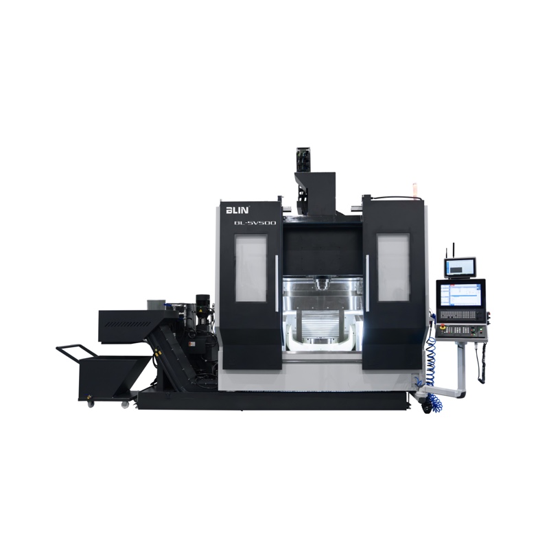
BL-5V500 Five-Axis Machining Center
Five-axis center with an overhead gantry rotary axis and linear guideway drives, part of a series of models designated 500, 700 and 900.
View ProductConclusion
A CNC milling machine is a cutting machine whose movement is commanded by a computer, and its value lies in repeatability, complexity and set-up data rather than in raw metal removal rate. The machine itself is only the visible part of the decision. What determines how it performs is the casting and its aging, the guidance system, the preloaded ball screws, the spindle power and the thermal behavior, and how honestly those are described. A buyer who asks for the envelope, the material, the tolerance with its measurement method, and the support arrangement will choose more accurately than one who compares speed figures alone.
For readers comparing CNC milling machine manufacturers, BLIN provides published specifications, technical documentation and direct inquiry channels for further evaluation.
FAQ
Is a CNC milling machine the same thing as a machining center?
They describe the same family of machine. A machining center is a milling machine built as a production cell, with an enclosure, an automatic tool changer, coolant and chip removal as standard, and often probing. A CNC milling machine is the broader term, and it includes the smaller knee-type and bed-type machines that have no enclosure.
What does the computer actually control?
It controls the position of each axis and the speed of the spindle, and it manages the tool change sequence, the offsets and the probe cycles. It does not control the forces in the cut, the thermal growth of the column or the accuracy of a worn slide, which is why machine accuracy and control resolution are separate subjects.
How accurate is a CNC milling machine?
General purpose vertical machines are usually specified at a positioning accuracy of a few hundredths of a millimeter, and precision machines at a few thousandths. The figure is only meaningful together with the test method, the machine condition at the time of the test and the standard used, so a comparison should require all three.
Is a five-axis machine worth the extra cost?
For a part with features on several faces, tight relationships between them, or deep contours that need a short stiff cutter, the saving in setups and in accuracy usually justifies it. For prismatic parts with two or three accessible faces, a three-axis machine is faster to program, easier to prove out and cheaper to run, and the extra axis adds nothing.
What maintenance does a CNC milling machine need?
A daily check of the way covers, the coolant level and the chip conveyor, a weekly check of the coolant concentration and filter, and an annual service covering the lubrication of the guideways and ball screws, the spindle bearing and the way covers. The schedule follows the working hours and the environment rather than a fixed date, since a machine in a dusty shop and one in a clean room do not accumulate dirt at the same rate.
References and Notes
Guidance on work equipment and machinery safety — the duty to assess machinery as installed rather than as delivered (hse.gov.uk, accessed 2026-11-19)
Calibration services for precision instruments — why a measurement claim is only as good as the method and the reference behind it (nist.gov, accessed 2026-11-19)
MTConnect, the open standard for manufacturing equipment data interoperability — how control data is read by monitoring systems across mixed machine brands (mtconnect.org, accessed 2026-11-19)
Data notes: the spindle speeds of 8,000 to 12,000 revolutions per minute and the high speed figure of 20,000 are typical published ranges for vertical machining centers rather than values fixed by a standard. The BT50 spindle with 15 kW or 18.5 kW motors, the 1.8 second tool change, the 36 m/min rapid traverse, the 2050 mm X axis stroke, the ±0.004 mm positioning accuracy and ±0.003 mm repeatability, the 1000 mm to 2000 mm table lengths, the 1600 kg table load, the 24T arm type tool changer and the BT40-150 spindle are the manufacturer's published figures for the models named. The positioning accuracy of the machines is quoted by the manufacturer and should be requested with the test method and the machine condition when comparing offers.